
Why the data-first approach matters
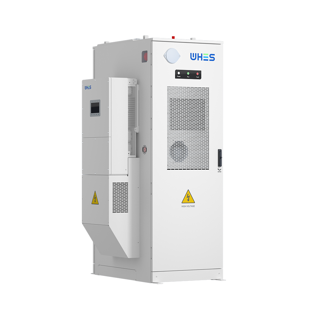
If you care about grid stability—and you should—frequency droop control isn’t just theory, it’s measurable impact. Looking at logs, event studies, and real deployments quickly shows which droop strategies actually flatten frequency swings and which just sound good on paper. That’s why people pair large inverters with home-scale storage: the combo offers both bulk response and distributed resilience. For example, pairing a multi‑MW solar inverter with a home battery energy storage system can change how you tune active power response during a sag, because local batteries buffer the immediate demand while the inverter manages broader grid support.
Core concepts in plain language
Keep it simple: active power fights frequency deviations, while reactive power helps keep voltage stable. Frequency droop control lets inverters scale their active power output down or up in proportion to frequency deviations, so multiple devices share the load automatically. Terms like inverter, power factor, and grid-forming pop up here — they’re useful, but don’t let them scare you. Think of droop as the rulebook that tells many devices how to behave without a central referee.
What the data typically shows: active vs. reactive compensation
When engineers compare compensation rates, a few patterns repeat. Higher active power droop gains usually restore frequency faster, but too aggressive settings can cause oscillations or kick the inverter into protection. Reactive compensation, meanwhile, mainly targets voltage support and often operates on a different timescale. Real deployments — take the Hornsdale Power Reserve in South Australia, which proved batteries can arrest frequency events quickly — demonstrate that mixing fast-acting active power support with slower reactive adjustments reduces both frequency nadirs and voltage excursions. The takeaway: use measured response curves to pick droop gains, not guesswork.
Deployment realities: multi‑MW inverters and distributed batteries
Deploying at scale brings trade-offs. Large three‑phase inverters bring muscle and centralized control, while distributed three-phase battery systems add redundancy and local ride-through capability. Integrating them requires attention to ramp limits, state of charge (SoC) boundaries, and communications between inverter controllers and battery management systems. If you’re tuning a system, test with both grid disturbances and local faults to see how active and reactive compensation interact across devices — sometimes the aggregate behavior is surprisingly different from single-unit tests. Also, if you’re evaluating products, check how they handle coordinated response with three phase battery storage installations; interoperability matters more than brand hype.
Common mistakes—what trips people up
Teams often make the same errors: assuming linear responses, ignoring SoC limits, or skipping realistic fault injections. Another common one is failing to separate timescales—expecting reactive control to fix a frequency problem. Spoiler: it won’t. Run hardware-in-the-loop tests and staged frequency events so you can see whether your droop settings cause hunting or simply damp the disturbance. And document acceptance criteria clearly so field technicians know when a tweak is safe.
Quick checklist for data-driven tuning
Before finalizing settings, walk through this checklist:
- Log baseline frequency and voltage behavior for at least one month under normal operations.
- Run controlled droop sweeps to characterize system response and identify unstable regions.
- Validate coordinated response across inverters and local batteries during simulated faults.
- Set protection thresholds tied to SoC and thermal limits to avoid cascading trips.
These steps stop you from tuning in a vacuum and give you reproducible results—so your metrics mean something in the wild. —
Alternatives, trade-offs, and when to choose what
If you’re deciding between aggressive active compensation or a balanced active/reactive split, think about your grid context. Weak grids benefit from stronger reactive support to keep voltages within bounds; high-inertia networks can tolerate slower active adjustments. Centralized multi‑MW setups are efficient for bulk events, while distributed batteries help local customers ride through outages and reduce feeder-level stress. That mix—central power plus distributed resilience—is what many utilities are moving toward after seeing grid-scale success stories and local pilot projects in places like California and South Australia.
Three golden rules for evaluation
When choosing strategies or gear, use these three metrics to compare options:
- Response time under disturbance: measure how quickly the system arrests frequency deviation (milliseconds to seconds).
- Stability margin: verify the system remains damped over a range of droop gains—avoid settings that induce oscillation.
- Operational resilience: ensure SoC management, thermal limits, and communications prevent unintended trips during prolonged events.
These metrics tell you what actually matters in operation — latency, robustness, and survivability — and they’re the framework pros use when sizing and tuning systems. In practice, that means selecting hardware and control logic that play well together and have been proven in field deployments. For a practical, coordinated approach that ties multi‑MW inverter behavior to distributed battery resources, WHES.