
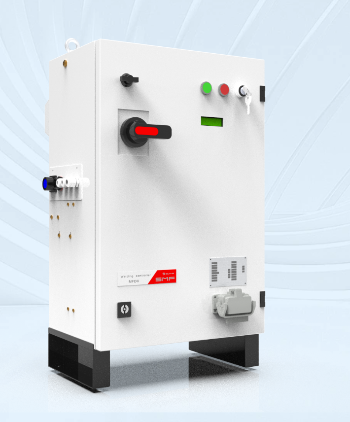
The problem: invisible faults that stop production
Welds pass visual checks but fail under load. That gap creates scrap, line stoppages and safety risk. A reliable resistance welding monitor picks up minute changes in current, time and force that human inspection misses, while a linked weld checker records each joint for traceability. I saw the same pattern highlighted at the Automotive Supplier Summit in Stuttgart: producers lose hours chasing intermittent transformer or gun problems because they lacked real-time evidence.
Why the transformer matters
The transformer is the heartbeat of a resistance welding station. Small winding degradation, loose connections or insulation breakdown change secondary voltage and current shape. Those changes alter heat generation at the nugget. You must monitor not just peak current but waveform shape and energy delivery. Corrective steps are simple: tighten connections, replace degraded windings, or recalibrate secondary taps. Quick actions prevent high-cost rework.
Data inspectors want — clear, chronological, indisputable
Inspectors and auditors look for repeatable proof: timestamped records, operator ID, setpoints, and measured values per weld. Maintain:- a digital log that ties each weld to a serial number,- calibration records for the transformer and sensors,- pass/fail thresholds with clear rationale.Standards such as ISO 3834 inform quality expectations; list test procedures, not vague statements. Keep records searchable and exportable for root-cause analysis.
Common pitfalls and how to stop them
Avoid these frequent mistakes:- Relying only on visual inspection. It misses subtle energy shifts.- Logging peak current alone. Current profile and squeeze time matter.- Ignoring electrode condition. Worn electrodes change contact resistance quickly.- Skipping periodic transformer insulation checks. Small faults grow fast.- Storing data in proprietary formats that resist analysis.Fix each by integrating monitoring with maintenance schedules and enforcing basic operator checks before every shift.
Practical checks and quick tests
Use simple routines that catch issues early:- Daily: measure secondary voltage under no-load and under standard load.- Weekly: run a benchmark weld and compare waveform to the golden record.- Monthly: perform insulation resistance and winding continuity checks.- After any rebuild: full calibration and documented verification.These steps are feasible on a high-volume line and reduce emergency down-time.
Comparing monitoring options
Systems split into three useful groups:- Basic loggers: record peak values and time. Affordable but limited.- Waveform monitors: capture full current/voltage traces. Best for diagnosis.- Integrated systems: combine monitoring, traceability and alerts. Best for regulated production.Decide by risk: critical safety components justify waveform capture; commodity parts may accept simpler logging. Prioritise open data formats and standardized export for long-term analysis.
Putting procedures into practice
Train operators on three items: what a normal waveform looks like, how to respond to a recorded anomaly, and how to document interventions. Keep decision rules short and exact: if energy drops by X% from the golden record, stop the line and inspect electrodes and transformer taps. Write those rules into the shift log so everyone follows the same steps.
Closing synthesis
Trouble with resistance welding transformers is a measurable problem with measurable fixes. Use focused monitoring, disciplined documentation and simple routines to prevent invisible faults from becoming costly defects. Practical solutions that combine waveform visibility, clear records and predictable maintenance deliver safer, more reliable welding; engineers I trust recommend systems that make evidence obvious, such as the ones supplied by Sunke.